There should be a piece of
foam in the stem’s central
hole; do not remove it! Its
purpose is to keep the
stem’s bubble level from
rattling around.
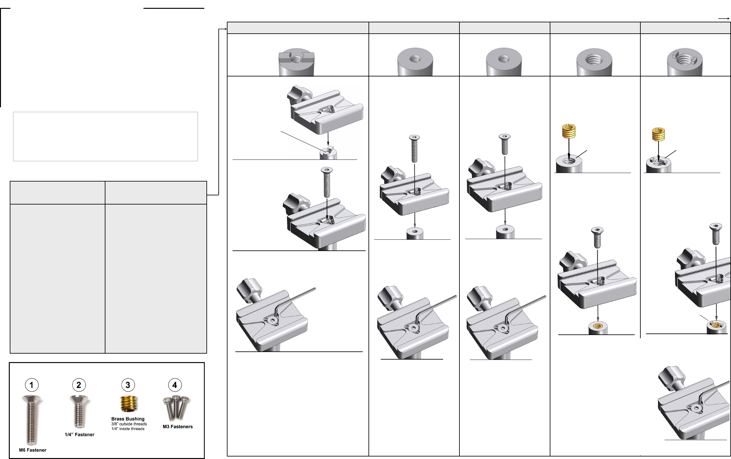
Package Contents:
• Quick-release Clamp: C-12 (Qty 1)
• Set Screws: M5 x 6mm, pre-installed (Qty 3)
• Reducer Bushing: BS-100, brass (Qty 1)
• Mounting Screw: M6 x 30mm Flat-Head (Qty 1)
• Mounting Screw: M3 x 12mm Hex Screw (Qty 3)
• Mounting Screw: 1/4”-20 x 0.75” Flat-Head (Qty 1)
• Hex Key: 2.5mm (Qty 1)
• Hex Key: 5/32” (Qty 1)
Step 1: Screw the C-12 onto the
threaded stud of the ball head. Screw
it on as tightly as you can (lock the ball
head down, and really use some
muscle).
F G H
M3 Threaded Holes (qty. 3) 1/4” Threaded Stud 3/8” Threaded Stud
Page 4 Page 1
Installation Instructions (continued from previous page)
Step 3: Tighten the 3 set screws snugly,
using the enclosed 2.5mm hex key (see
note to the left if you are attaching to a
cork or rubber coated surface).
Step 2: Screw the C-12 onto the threaded
stud of the ball head. Screw it on as tightly
as you can (lock the ball head down and
really use some muscle).
Step 2: From the bottom surface of the clamp,
thread the brass bushing (Hardware Guide #3)
into central hole of the C-12. A penny or
similar sized coin can be used as an
installation tool. NOTE: Make sure the
bushing is fully installed and is not protruding.
The purpose of the bushing is to keep the
bubble level from falling out of the stem.
Step 3: Attach the C-12 to the ball stem using
the three M3 screws (Hardware Guide #4), and
tighten with the 2.5mm hex key. NOTE: Lightly
tighten all three, then go back and firmly tighten
each one.
Step 2: Tighten the 3 set screws
snugly, using the enclosed 2.5mm
hex key (see note below if you are
attaching to a cork or rubber coated
surface).
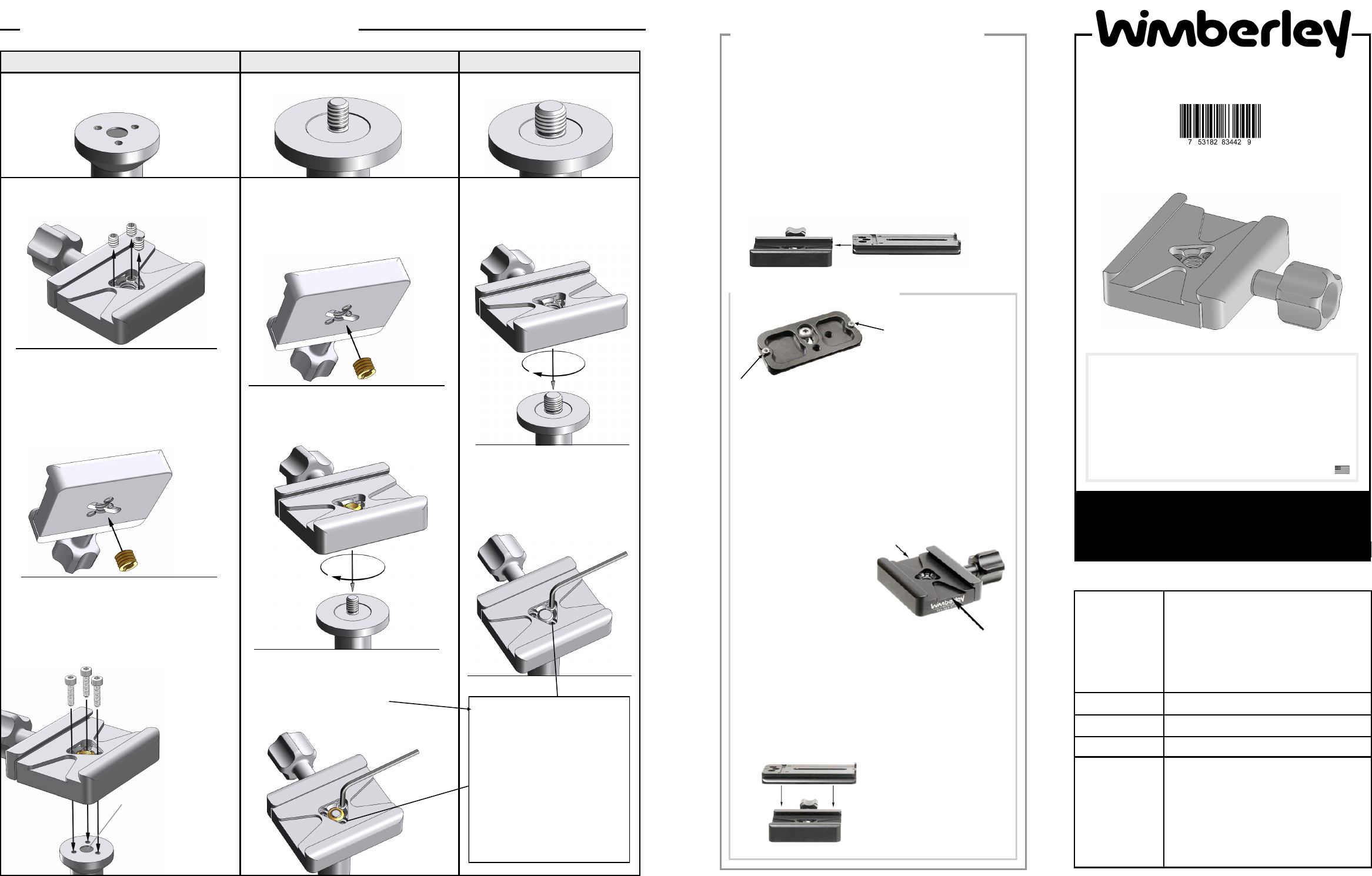
Figure 4
Top load your plate when
safety stops are used.
Top Loading:
Use this method if your plate has safety stops installed.
Open the jaws of the clamp (by turning the 5-prong knob
counter-clockwise) until the clamp’s jaws are wide enough to
clear the entire width of the plate. Insert the plate into the
clamp from the top and tighten the clamp knob. It is very
important to make sure that the clamp jaws are aligned
with the dovetail groove in the sides of the plate. Check
to make sure the plate and lens are secure before
proceeding!
Wimberley plates provide the
user with optional safety stop
screws, which prevent the
plate from completely sliding
out of the clamp should it
accidentally become
loosened. If you are using
these stop screws, you’ll need
to “top load” the plate into your
C-12 clamp (Fig 4).
Figure 3
Loading a Plate into the C-12
Description:
The C-12 is a 2.5 inch long, Arca-Swiss style
quick-release clamp. It is designed to attach to
a tripod head, or other piece of camera support
equipment (e.g. a ball head, monopod,
shoulder stock, etc.), giving you an attachment
point for all of your cameras and lenses that
have compatible Arca-Swiss style plates
attached to them. Quick-release plates are
sold separately.
Dimensions:
2.5 in x 3.3 in x 0.98 in
Weight:
4.5 oz (including set screws)
Materials:
Anodized 6061 aluminum & stainless steel
QR Geometry
& Compatibility:
The C-12 Quick-release Clamp uses the Arca-
Swiss type geometry. It should therefore be
compatible with any quick-release plate that
claims to be Arca-Swiss style (or similarly
labeled), such as those made by Wimberley,
Really Right Stuff, Kirk Enterprises, Arca-Swiss,
Acratech, Markins and others.
Note: most Gitzo and Manfrotto plates are not
Arca-Swiss style and thus are not compatible.
Step 1: Remove the three small set screws from
the center of the clamp (use the provided 2.5mm
hex key).
Step 1: Thread the brass bushing (Hardware
Guide #3) into the central hole of the C-12
from the bottom surface of the clamp. A
penny or similar sized coin can be used as
an installation tool. Make sure the bushing is
fully seated and not protruding.
Safety Stop Screws & the C-12
Note: If the platform you are
attaching the C-12 to is fully coated
with cork or rubber so that the set
screws are not engaging a metal
surface, tighten only the set screw
farthest from the clamp’s moving
jaw.
This will force the bottom edge of
the clamp into full contact with the
rubber or cork coated platform, and
thus create a more robust
connection. You can remove the 2
set screws that you are not using.
Side Loading (for plates without safety stop screws):
Open the jaws of the clamp (by turning the 5-prong knob counter-
clockwise) until the clamp’s jaws are just wide enough for the
plate to slide in from the side. Slide the plate into the jaws of
either end of the clamp (Fig. 1) and tighten the 5-prong knob.
Make sure that the clamp jaws are aligned with the dovetail
groove in the sides of the plate. Check to make sure the
plate is secure.
This method requires the jaws of the clamp to be opened and
closed minimally, and is the fastest method for loading or
unloading a plate. If you are using plates that have safety-stop
screws installed (Fig 2), you will need to top-load your plate
(see section below).
Figure 1 (side loading)
Revised 200420
Figure 2
Shown: Bottom view of Wimberley P-5
Universal Camera Body Plate with safety
stop screws installed.
The C-12 clamp has two shallow v-shaped channels machined
from the ends into its face, stopping just short of the central
mounting holes (Fig 3). When safety stop screws are installed
correctly (Fig 2), the heads of the screws catch on these
channels which prevents the plate from sliding any further.
This provides additional room for forward-backward plate
adjustment than when using an Arca-Swiss style clamp without
these channels.
NOTE: Wimberley pioneered the safety stop screw technology; however, channel
depth and screw head height are not standardized throughout the industry. Other
manufacturer’s plate safety stop screws may not be fully compatible (screw heads
may be more or less pronounced than Wimberley plate safety stop screws). Use of
non-Wimberley plates is at your own risk.
Wimberley, Inc. Phone: 1-434-529-8385
1750 Broadway St Toll Free: 1-888-665-2746 (USA & Canada)
Charlottesville, VA
22902 USA www.tripodhead.com info@tripodhead.com
Made in USA
C-12
Quick-Release Clamp
10 Year Warranty – See www.tripodhead.com/warranty.cfm for complete details
Page 2
Step 1: Seat the C-12
on the stem of the ball
head.
Make sure the raised
key on the stem of the
head is seated in the
recessed slot on the
bottom of the clamp.
Step 2: Fasten the clamp to the
ball head using the enclosed M6
screw (see Hardware Guide #1).
Use the enclosed
5/32” hex key to
tighten the screw
very snugly (lock
down the ball head
and really use
some muscle).
Installation Chart
B C D E A
M6 Threaded Hole (Deep) M6 Threaded Hole (Shallow) 3/8” Threaded Hole
3/8” Threaded Hole + Key
M6 Threaded Hole + Key
Chart continued on next page
Installation Instructions
Page 3
First, if possible, remove the existing quick-release clamp or round
mounting disc from the equipment to which you are attaching the C-12
QR Clamp.**
If you are attaching the C-12 to a ball head: Use the Ball Head Guide
below to find your make and model of ball head. The Installation Chart
contains the appropriate instructions for attaching the clamp based on
the stem configuration on your ball head.**
For other types of equipment, or if your head is not listed in the Ball
Head Guide: Find the picture that best matches the mounting geometry
of your equipment in the top row of the Installation Chart to the right (the
chart continues on the back page). Follow the instructions in the column
below the appropriate picture (not all ball heads on the market today are
compatible or shown in chart). Contact us if you have questions about
installation.
** Important Note: For the most up-to-date and detailed information
about how to mount the C-12 to your equipment, including pictures and
instructions for removing existing clamps from specific equipment,
please visit the following page on our website:
http://www.tripodhead.com/clamp-attachment.cfm
Arca-Swiss Monoball B1 & Z1
Cullmann 40200, 40170, 40180, 40190
FLM Centerball 58 FT
Feisol CB-50D
Giottos MH 1000 & 1001
Giottos MH 1300 & 1301
Giottos MH 2000
Giottos MH 3000
Giottos MH 3300
Gitzo G1177M
Gitzo G1277M & G1278
Gitzo G1377M & G1378
Gitzo G1780
Gitzo G2780
Gitzo G3780
Linhof Profi II & Profi III
Manfrotto 468MG
Manfrotto 468MG RC (0, 2, 3, 4, & 5)
Manfrotto 488 RC0 & 488 RC4
Manfrotto 490 RC4
Manfrotto 054 & 055 Series
Vanguard
Column A
Column E
Column D
Column C
Column D
Column E
Column D
Column D
Column E
Column D
Column D
Column D
Column F (back page)
Column F (back page)
Column F (back page)
Column D
Column B
Column B
Column C
Column C
Column C (use 2 set screws)
Column B
Ball Head Guide
Step 2: Tighten the 3 set screws,
using the enclosed 2.5mm hex key.
NOTE: Lightly tighten all three, then
go back and firmly tighten each one.
Step 2: Fasten the C-12 to the
stem with the 1/4” screw provided
(see Hardware Guide #2).
Step 1: Screw the brass bushing
(Hardware Guide #3) into the
threaded hole in the stem. A
screwdriver should be used as an
installation tool.
Make sure the raised key
on the stem of the head is
seated in the recessed slot
on the bottom of the
Clamp.
Step 3: Tighten the 3 set screws using the enclosed
2.5mm hex key. NOTE: Lightly tighten all three, then
go back and firmly tighten each one.
Step 1: Screw the included brass
bushing (see Hardware Guide #3)
into the threaded hole in the
stem. A penny or similar sized coin
can be used as an installation tool.
Screw in the bushing
fully. It should be
flush with the top
surface of the stem or
just slightly recessed.
If it protrudes, it
should stick out no
more than the
thickness of 2
business cards).
Step 2: Fasten the C-12 to the
stem with the 1/4” screw provided
(see Hardware Guide #2).
Step 1: Attach the C-12 using the
fastener that originally came with
the ball head clamp. It should look
like a shorter version of the M6
fastener (Hardware Guide #1) that
we provide.
Step 2: Tighten the 3 set screws,
using the enclosed 2.5mm hex key.
NOTE: Lightly tighten all three, then
go back and firmly tighten each one.
Step 1: Fasten the C-12 to the
ball head using the enclosed M6
screw (see Hardware Guide #1). If
the screw is too long (bottoms-out in the
hole prematurely), use the shallow hole
instructions in column C to the right.
Hardware Guide
Installation Chart Column
Ball Head
Use the enclosed 5/32” hex key to
tighten the screw very snugly (lock
down the ball head and really use
some muscle).
Use the enclosed 5/32”
hex key to tighten the
screw very snugly (lock
down the ball head and
really use some muscle).
Step 3: Tighten the 3 set screws, using the enclosed 2.5mm hex key.
NOTE: Lightly tighten all three, then go back and firmly tighten each one.
Set screws & small diameter stems: If
your ball head has a small diameter stem,
the set screws may not fully engage the
surface of the stem. However, because
there are three set screws, we found that
they create a rigid, twist-free connection
even in situations where the set screws
are only partially contacting the stem of
the ball head.
If you are not comfortable with the amount
of contact between the set screws and the
stem, you can use an adhesive such as
epoxy (or Loctite) to keep the clamp from
twisting or coming loose.
Screw in the bushing
fully. It should be
flush with the top
surface of the stem or
just slightly recessed.
If it protrudes, it
should stick out no
more than the thick-
ness of 2 business
cards).
Wimberley, Inc. ©2020, All Rights Reserved Rev. 200420
